Levitra enthält Vardenafil, das eine kürzere Wirkdauer als Tadalafil hat, dafür aber schnell einsetzt. Männer, die diskret bestellen möchten, suchen häufig nach levitra kaufen ohne rezept. Dabei spielt die rechtliche Lage in der Schweiz eine wichtige Rolle.
Catalog lv 71 en, chapter


Welcome to Automation and Drives
Low-voltage switchgear –
the basis for progressive solutions
Totally Integrated Automation –
innovations for more productivity
Totally Integrated Power –
energy distribution and management
from one source
SIVACON 8PS –
Busbar Trunking Systems in Action
SIVACON 8PS –
Engineering Tools for precisely
dimensioned, economical solutions
Siemens LV 71 · 2004/2005
Welcome to
Automation and Drives
We would like to welcome you to Automationand Drives and our comprehensive range ofproducts, systems, solutions and services forproduction and process automation andbuilding technology worldwide.
With Totally Integrated Automation andTotally Integrated Power, we deliver solutionplatforms based on standards that offer youa considerable savings potential.
Discover the world of our technology now. Ifyou need more detailed information, pleasecontact one of your regional Siemenspartners.
They will be glad to assist you.
Low-voltage switchgear and controlgear –
the basis for progressive solutions
Everyday life would be unimaginable without electric power. Competence and innovations in switching and electrical installation technology are prerequisites so that power can be used without danger and user-friendly in industrial facilities and buildings. We have been providing you with these prerequisites for more than 110 years and are permanently de-veloping new features – innovations which permit you to use power more safely and eco-nomically.
Low-voltage switchgear from Siemens offers a comprehensive and innovative range of products covering switching devices for load feeders or the distribution of power, control and signaling devices as well as complete cabinet systems. Multi-functional, uniform con-cepts such as Totally Integrated Power, Safety Integrated or ECOFAST additionally permit our product portfolio to be combined into optimized systems.
All in all, we can provide you with innovative components for switching and electrical in-stallation technology which utilize state-of-the-art features such as integration and com-munication as the basis for advanced and uniform solutions which provide you with many benefits.
Totally Integrated Automation
innovations for more productivity
With the launch of Totally Integrated Automation in 1996, we
were the first ones on the market to consistently implement
the trend from equipment to an integrated automation
solution, and have continuously improved the system ever
Whether your industry is process- and production-oriented or
a hybrid, Totally Integrated Automation is a unique "common
solution" platform that covers all the sectors.
Totally Integrated Automation is an integrated platform for the
SIMATIC NET
ECOFAST IP65
entire production line - from receiving to technical processing
and production areas to shipping. Thanks to the system-oriented
engineering environment, integrated, open communications
as well as intelligent diagnostics options, your plant now
benefits in every phase of the life cycle.
In fact, to this day we are the only company worldwide that
can offer a control system based on an integrated platform
for both the production and process industry.
SIMATIC IT Framework
SIMATIC HMI
SIMATIC PCS 7
PROFIBUS PA
and Control
Totally Integrated Power
energy distribution and management
from one source
Totally Integrated Power by Siemens offers integrated
solutions for energy distribution in functional and industrial
buildings covering everything from medium-high voltage to
power outlets.
Totally Integrated Power is based on integration in
planning and configuration as well as coordinated products
and systems. In addition, it features communications and
software modules for connecting power distribution systems
to industrial automation and building automation, thereby
offering a substantial savings potential.
PROCESS FIELD BUS
Products and systems
£ 110 kV
Planning and configuration
Cost center
EMPLOYEECOST CENTER
PAY PERIOD BEGINNINGPAY PERIOD ENDING
Air conditioning system
central ON
Replacing circuit
instabus EIB

SIVACON 8PS –
Busbar Trunking Systems in Action
Busbar trunking systems in the low-voltge range perform the safe and reliable transmission and distribution of electrical power from transformer via main distribution board and sub-distribution board right to the load. Siemens busbar trunking systems are the complete and efficient answer in this area:• The CD system
• The BD01 system
for 40 A to 160 A
• The BD2 system
for 160 A to 1250 A
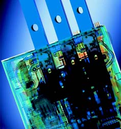
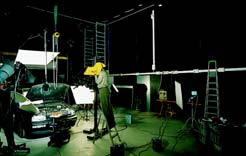
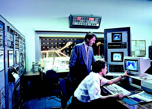
The BD 01 system is quick to install and ideally suited for use in workshops and
• The PEC system
for 800 A to 6000 A
trade premises, as here, at a photo-
• The LD system
for 1100 A to 5000 A
• The LX system
for 800 A to 6300 A
Alle these systems are 'Type-tested LV switch-gear assemblies' (TTA) to IEC 60 439-1 and -2. This ensures that they offer a standard of safety and reliability that meets the particularly high performance expectations of automated pro-duction and for building services provision.
Performance characteristics:• Clear network structure• Unproblematic retrofitting in the event of load
• Low operating costs due to uninterrupted ser-
• Simple planning and installation
The ideal system for production lines needing a great deal of power is the LD system up to 5000 A.
Room-covering systems for lighting installa-
tions and small loads
The CD system (up to 40 A) allows you to supply
lighting installations covering the whole expan-
se of, say, furniture showrooms, supermarkets
or greenhouses with power, and also provides
the means to easily fix them in position.
Due to its pleasing appearance, the equipment
is well suited for use in sales rooms visited by
the public. On the other hand, its high degree of
protection, to IP54, allows the CD system to be
used even in harsh environments.
The power source for loads with no fixed
location
The BD01 system is ideally suited for the power
supply (up to 160 A) in workshops and trade
premises. The trunking units are easy and quick
to put together. The anti-rotation feature on the
tap-off units makes sure that the units are
correctly fitted and allows for easy retrofitting
even while the production is running.
Other benefits: minimum stock holding and un-
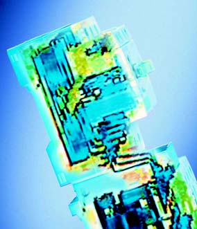
In the petrochemical industry, it is the PEC system that provides reliable and fault-free power supply.
complicated planning due to one standard frame size for five different current ratings.
Universal power distribution
The BD2 system (up to 1250 A) can supply
power to medium-size loads in buildings and in
all industrial applications. Prefabricated tap-off
units fitted with many differing component
combinations make this equipment universally
applicable. Two standard frame sizes covering
all current ratings simplify stock keeping and
planning.
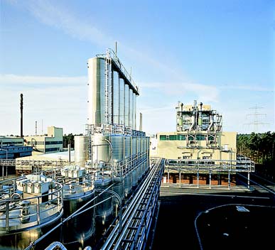
Safe and reliable power transmission in the
petrochemical industry
The PEC resin-insulated system, up to 6000 A,
has a high degree of insulation protection and
thus an enormous resistance to external interfe-
rence factors. This ensures safe and reliable
transport of power even in rough weather or in
highly dust and dirt and corrosion polluted
industrial environments. Typical applications of
this system is the petrochemical industry, waste
incinerators and power stations.
Siemens offers modular component cabinets for indication, control and monitoring of the flow of power through busbar trunking systems. These cabinets are equipped with bus
High system serviceability in production
interfaces, control circuit devices and power meters.
The louvred LD busbar trunking system, up to 5000 A, is the system for transporting current in production lines with a large energy require-ment, such as in the automotive industry. A separate PE busbar ensures that the protective device in such a system responds reliably even if the current paths are relatively long. The high short-circuit rating allows medium-voltage switches to be used as protective elements for the transmission of power between transformer and main circuit-breaker. Tap-off units up to 1250 A available as standard.
Flexible power distribution in multi-storey
buildings
The LX sandwich-style system, up to 6300 A, is
used where large quantities of power need to be
transported, uninfluenced by the mounting posi-
tion of the system.
Conductor configurations with the PE conductor
insulated along its entire length, and a double-
size neutral can ensure the interference-free dis-
The LX busbar trunking system is the perfect equipment for multi-storey buildings where large quantities of power need to be transpor-
tribution of power in places such as radio
ted, uninfluenced by the mounting position of the system.
stations, computer centres or at internet providers'. The system is protected to IP54 as standard, and tap-off units up to 1250 A availa-ble as standard.
SIVACON 8PS - Engineering Tools for
precisely dimensioned, economical solutions
Engineering tools from Siemens help generate precisely dimensioned and economical plan-ning and design solutions, even for complex ap-plications.
MatSelect
Using MatSelect, product and material data can
be administered with self designed or
standardised classification systems. It has inter-
faces to Eldanorm, Datanorm, ASCII format and
ProPlan.
NetPlan
Planning software for power flow, short-circuit
calculation and device dimensioning with selec-
tivity analysis and protective against electric
shock of low-voltage networks, available in
English, German, French and Italian.
NetPlan enables you to graphically represent the network and to
Selection software for protective switches to en-
calculate the load flow and the prospective one-pole to all-pole short
able star networks to be correctly dimensioned;
available in several languages.
BusbarSelect
Selection aid for generating quotations, invitati-
ons to tender and orders for busbar trunking
systems up to 1250 A; available in several
languages.
Quotation texts
Prepared texts (in German) for generating
customer specifications in the formats: Architext
excellent, GAEB 81 and Word 97.
Should you have any queries concerning instal-lation, functionality or application options – please mail us [email protected] will be pleased to assist you.
In BusbarSelect, you select the trunking units for your system from a menu, and then transfer them into an order or quotation list.
Busbar Trunking Systems,
Overview
Siemens LV 71 · 2004/2005
Busbar Trunking Systems, Overview
Technical Overview
Busbar trunking systems
Rated operational
active conductors
IP54 with accessories, IP55 on request
LDA1 – LDA8
LDC2 – LDC8
LXA01 – LXA10
LXC01 – LXC10
IP55 with accessories
Siemens LV 71 · 2004/2005
Busbar Trunking Systems, Overview
every 0.5 or 1 m
Can be combined with networkable
tap-off units for lighting control sys-
painted sheet steel housing
Al or Cu busbars,
Can be combined with networkable
(without tap-off
tap-off units for lighting control sys-
tems, remote switching and load mon-
Information about the LD and
Al or Cu busbars,
(without tap-off
LX systems: from your
Siemens sales outlet.
Can be combined with networkable tap-off units for remote switching and load monitoring
Al or Cu busbars,
(without tap-off
Siemens LV 71 · 2004/2005
Busbar Trunking Systems, Overview
System Overview
Siemens LV 71 · 2004/2005
Busbar Trunking Systems, Overview
Up to 6300 A
CD system
LX system
Reduced planning costs by simplified engineering
The busbar trunking system for power transmission and distribution in
Quick-release plug-in connection for fast assembly
Tap-off points on both sides for optimized utilization of the busbar
Detailed information about this system is available from your Siemens sales outlet.
Even electrical loading of the CD system conductors achieved by connect-ing an equal number of tap-off plugs to each individual phaseVersatility through high degree of protection to IP54 of the standard
PEC system
The busbar trunking system for power transmission under extreme environ-
Tap-off plugs allow fast, flexible load relocation (even on live sytems).
mental conditions (IÜP68).
Detailed information about this system is available from your Siemens sales outlet.
Up to 160 A
Networkable busbar trunking system
BD01 system
Networkable function expansions for combination with known tap-off
Flexible power supply
Junction units for changes in direction
Quick, straightforward planning
– large area lighting control systems– remote switching and signalling in industrial applications
Time-saving assembly
– load monitoring of decentral power tap-offs
Reliable mechanical and electrical connections
EIB, AS-i and PROFIBUS bus systems
High level of stability, low weight
Quick, straightforward planning
Positive opening and closing of tap-off points
Flexible with expansion and modification
Versatile tap-off units
Few basic elements
Can be retrofitted to existing installations
Modular system reduces stock-holding
Simple contact establishment of bus line with insulation displacement
High degree of protection to IP54 with tap-off points at sides and bottom
connection feature
for extreme ambient conditions, otherwise IP50.
Can be used with the BD01, BD2, LD, and LX systems
Up to 1250 A
BD2 system
Design software for busbar trunking systems up to 1250 A
Quick, straightforward planning
This CD-ROM is available free of charge from your Siemens sales outlet.
Time-saving, cost-efficient assemblyReliable, safe operationFlexible modular system with simple solutions for every application
Early planning of power distribution possible without precise knowledge of
consumer locations
Fast operational readiness through quick, easy assembly
High degree of protection to IP54 for use in harsh industrial environments
Busbar trunking systems BD2A/BD2C and LDA/LDC from 160 A to 5000 A
Innovative construction:
No compensating units for expansion compensation required.
Planning guideSIVACON 8PS
Busbar trunking systems LXA/LXC over 800 A
These planning aids are available from your Siemens sales outlet.
Up to 5000 A
LD system
The busbar trunking system for optimized power distribution in industry.
Reliable, safe operation
Time-saving, cost-efficient assembly
Safe and flexible power distribution up to 6300 A
Space-saving compact construction type up to 5000 A in an enclosurePlug-in tap-off units up to 1250 AType-tested connection to service distribution boards and transformers
Siemens LV 71 · 2004/2005
Busbar Trunking Systems, Overview
Notes
Siemens LV 71 · 2004/2005
LD Busbar Trunking System
Engineering
Examples
Engineering of vertical busbar runs
Degree of protection
Vertical runs may be designed to degree of protection
IP34 or IP54.
The type suffix L+LD-L120.-X.(Y.) is used for LDA and LDC systems. The centre of the fire barrier is always the centre of the fire ceiling thickness �.
For LDA 8 and LDC 8 systems, the length of the outer fire barrier is 0.68 m (otherwise 0.48 m).
Where possible, the fire barrier should be provided on standard trunking units.
For straight trunking units for vertical installation with-out any tap-off point(s), the closest fire barrier position is at X = 1.10 m due to the position of the expansion com-
For straight trunking units for vertical installation with a tap-off point AD 1,4, the closest fire barrier position is at X = 2.05 m (X = 1.95 m for LDA(C) 8).
For trunking units with a tap-off point AD 1,8, the closest fire barrier position is at X = 2.45 m (X = 2.35 m for LDA(C) 8)
The hooks must always point downwards with the hook opening pointing towards the wall �.
There should be a clearance of at least 0.48 m (LDA(C) 8 = 0.58 m) from the centre of the ceiling to the bolt end �.
The fixing elements must be fitted about 0.45 m below the ceiling �.
At least one pair of fixing brackets is required per trunk-
The adjustment capability of � 50 mm allows wall unevenness to be compensated for �.
The wall clearance with the LD busbar system when using vertical fixing brackets is at least 20 mm �.
When engineering tap-off points, trunking units for vertical engineering with integrated expansion and an integrated fixed point must always be used .
� Centre of fire barrier is always the centre of the fire ceiling.
� Hook always downwards with hook opening pointing
towards the wall.
� Minimum distance between the centre of the ceiling and the
bolt end: 0.48 m (LDA(C) 8 = 0.58 m).
� Fixing element clearance.
� At least one pair of fixing brackets is required per trunking
� Wall unevenness is compensated for by ± 50 mm adjustment
Siemens LV 71 · 2004/2005
LD Busbar Trunking System
Engineering of trunking unit lengths
• Height of storeys up to 3.2 m
– The trunking unit length is equal to the height of
• Heights of storeys greater than 3.2 m
– Trunking units with standard limb lengths should be
– A vertical trunking unit can be combined with a
maximum of one standard trunking unit.
The following table should be used only as a rough guide for engineering design purposes.
Trunking unit for
Trunking unit for
Height of ceiling 2.75 m, Ie = 1100 A
Degree of protection IP34, 4-conductor system, with fire barrier, tap-off point at X = 1.4 m
Selected trunking unit: LDA 1423-V-1W2,75-AD1,4 +LD-L120A-X2,27.
Straight trunking units with tap-off point(s) must always be trunking units for vertical installation.
Height of ceiling 4.80 m, Ie = 2400 A
Degree of protection IP54, 5-conductor system, without fire barrier
Selected trunking units: LDA 7615-V-3W3,2, LDA 7615-1,6.
Siemens LV 71 · 2004/2005
LD Busbar Trunking System
Engineering
Examples
• Number and height of the storeys
• Ratings per storey and types of load• Utilization and rated load factors• Feed transformers (characteristic data, position)• Special requirements (degree of protection, fire barrier
• Number and size of the height adjustments (> 1.3 m)
• Number of coded tap-off points required.
• 11 storeys each with 8 residential units• Rating 38 kW per residential unit• Ue = 400 V, p. f. = 0.8, 5-conductor system,
degree of protection IP54
• Rated load/utilization factor: α = 0.7, β = 0.45• Feed from the distribution board via LD connection
• Transformer rating = 1600 kVA• Details and construction plans required for engineer-
• Tap-off units to be positioned at eye level.
The rated current per storey is calculated using the fol-
lowing formula. The formula also allows the rated cur-rent for the tap-off units to be defined.
= --------------------- × 10
3 × U × cosϕ
= Rated current per storey (A)
= Rated operational voltage (V)
Pinst = Total installed power per storey (kW)cos ϕ = Power factor (p. f.)
= Rated load factor
1) If � is not stated, the values from the "Number of main cir-
cuits" table may be used. If the p. f. is not stated, this may be assumed to be = 1 for purely domestic high-rise buildings.
= --------------------- ×
For item numbers refer to the parts list for the engineering example
Siemens LV 71 · 2004/2005
LD Busbar Trunking System
The rated current per busbar run is calculated from:
Unless the application necessitates a change, the rated load factor from EN 60439 may be used for α.
Number of main circuit
= Rated current (A)
β2) = Utilization factor for the total number loads
2) The local PESs have good empirical values for utilization
6 to 9, inclusive
factors; these differ between regions. Average values are given in the "Type of Load" table.
Notes relating to the engineering example
Since the rated current for IP54 vertical is the same as for
LDA 6515 is chosen here since IB is reduced from 3100 to
horizontal systems, the complete run may be engineered
2000 A because of the degree of enclosure protection
using LDA 6615.
Average values are always quoted for the utilization fac-
Once the system has been selected, the following docu-
ments are produced for the order:• Installation plan using the LD engineering tool
Types of load
Dwellings with electric cookers and
• Parts list generation using the LD engineering tool
(for about 100 connections)
• Binding order
Off-peak storage heaters
Lighting in office buildings and in
buildings for commercial use
Lifts and general installations
Parts list relating to the engineering example
Max. rated current
Distribution board connection units for LD
connection to ID 2000
Straight trunking unit (optional length with
LDA 6615-LVR-Y1,13
Offset elbow with longer Y-leg and fire
LDA 6615-K-V-2,4-AD1,4
Straight trunking unit for vertical installation
with one tap-off point
Straight trunking length (optional length)
with fire barrier
End flange with hook
Tap-off unit with fuse switch-disconnector
Fixing bracket for vertical installation
Siemens LV 71 · 2004/2005
LD Busbar Trunking System
Engineering
Tap-offs
Tap-off units
All tap-off units have the following common features:• Galvanized steel enclosure with paint finish• Handles for fitting, removing or transporting the tap-
• Door or removable cover• Guide and fixing elements for mounting on busbar
• Contact protection for fitting/removing
Safety during handling
Early-make PE or PEN
Tap-off with early-make and late-break PE or PEN con-ductor contact when fitting or removing the tap-off unit. In the 5-conductor system, the PE connection is made via sliding contacts on the coding brackets. In the 4-conduc-tor system, this is provided by a longer PEN bar on the contact apparatus.
A 7-conductor system (N/PEN = ½ L) is shown by way of example below.
4-conductor (TN-C system)
5-conductor (TN-S system)
� Coding brackets
A specified sequence of operations ensures that no load
The LDA(C) system enables tap-off units to be fitted and
current can flow when fitting or removing the tap-off
removed whilst the entire LD system is still energized.
All live parts are finger-proof during fitting and removal (IP20).
Correct orientation and installation
The tap-off units should only be opened when the pro-
Coding brackets on the tap-off unit and on the tap-off
tective device is open, i.e. switched off.
point of the trunking unit (key-lock principle) prevent the tap-off units from being fitted incorrectly on the tap-off
All live internal live parts are finger-proof.
This prevents the tap-off unit from being fitted in the opposite way round on tap-off point and ensures the cor-rect allocation of 4- and 5-pole LD systems.
Siemens LV 71 · 2004/2005
LD Busbar Trunking System
Relationship between the hook opening (phase sequence) and the tap-off unit cable entry
With the tap-off "above"=-AD, the cable entry is from the hook end.
LD.-K-AD� Cable entry at the end� Cable entry at the side
With the tap-off "below"=-ADU, the cable entry is from
Illustration of a coding bracket in a 4-pole system
the bolt end.
LD.-K-ADU� Cable entry at the end� Cable entry at the side
When tap-off units are mounted on straight trunking units for vertical installation (-V-AD), cable entry is from the hook end.
Illustration of a coding bracket in a 5-pole system
Protection against direct contact
Degree of protection IP20 is provided at the open tap-off point on the trunking unit and on the contact system of the tap-off unit.
Cable connection safety feature
A plate which separates the cable connection area from the component mounting area within the tap-off unit
prevents cables being inserted from touching live parts.
LD.-K-V-AD� Cable entry at the end� Cable entry at the side
Trunking units for vertical installation must always be used when engineering tap-off points for vertical use and with adjustments in height >1.3 m.
Siemens LV 71 · 2004/2005
LD Busbar Trunking System
Engineering
Tap-offs
Tap-off units GSTA fuse switch-disconnectors
Degree of protection
The compact design means that one size covers all cur-
Degree of protection IP 30 is standard. The high degree
rent ratings.
of protection IP 54 (type suffix) can be provided just by fitting an additional cover either at the factory or directly
The rated currents extend from 125 A to 630 A; and 1 × GSTA 00 or 2 × GSTA 00 may be selected for the 125 A version.
Safety during fitting/removal while the system is live is achieved by a specified fitting/removal sequence, see the relevant intallation instruction, and by subsequent open-ing of the cable connection area after releasing 2 fixing screws. The cover cannot be removed until the top sec-tion of the fuse switch-disconnector has been removed.
Degree of protection IP30
Degree of protection IP54
Siemens LV 71 · 2004/2005
LD Busbar Trunking System
Cabling box and cable entry
Tap-off units with GSTZ fuse switch-disconnectors
• The bolt connection is designed for cables up to
• The standard tap-off unit version has an end cable
There is one size of the tap-off unit. It can accommodate both, GSTZ 2 or GSTZ 3.
• Where side cable entry is required, a cabling box (type
suffix) can be flange connected at the factory or directly on site.
Cable entry at the end
The rated currents are 400 A and 630 A, respectively.
Safety by design
The fixed procedure for fitting/removal of the tap-off unit provides protection against mishandling.
Degree of protection
Degree of protection IP30 without door is standard. The high degree of protection IP54 can be achieved by fitting a door (type suffix).
Cable entry at the side
Door hinging
A cable entry plate for a maximum of 3 multi-core cables
The doors may either be supplied with "door hinged on
up to 300 mm2 is standard. The cables are supported by
the left" or "door hinged on the right". When ordering,
an integral cable anchoring rail in the tap-off unit
the type suffix +LD-TL. or +LD-TR. must be used for this
(bracket clamps to be supplied on site). An undrilled alu-
minium entry plate for customized fitting with cable glands on site, for single core cable entry can be obtained
The door hinging may be converted on site.
by stating the relvant type suffix.
The bolt connection is designed for cables up to 300 mm2.
Sealing for the NH fuse switch-disconnector sizes NH 00
The standard version is available with end or side cable
and NH 01 is standard. (Sealing for sizes NH 2 and NH 3
on request).
For multi-core cables, the split cable entry flange is designed for a maximum of 2 multi-core cables up to 300 mm2.
For single-core cables, the cables are inserted through a drilled aluminium plate with PG cable glands. The num-ber and size of the glands may be found in the Technical Data section.
The cables are held by a cable anchoring rail within the tap-off unit.
Siemens LV 71 · 2004/2005
LD Busbar Trunking System
Engineering
Tap-offs
Tap-off units with circuit-breakers
• High switching capacity (H) for size 1 (80 . 250 A)
• 2 sizes depending on the circuit-breaker in use:
and 2 (400 . 570 A)
– Size 1 for tap-off units with NZM 7 circuit-breaker
• Very high switching capacity (S for size 3 (800 A)1))
• Circuit-breaker with 3 or 4-pole versions
– Size 2 for tap-off units with NZM 10 circuit-breaker
• 4-pole circuit-breakers (TN-S system) are fitted with
– 100 % releases for 80 . 250 A (NZM 7)
– Size 3 for tap-off units with NZM 14 circuit-breaker
– 60 % releases for 400 . 570 A (NZM 10)
– 0 % releases for 800 A1) (NZM 14)
• The circuit-breakers are fitted with NHI and RHI
standard and trip-indicating auxiliary contacts as standard. A shunt or undervoltage release can be selected for the version with remote operator.
• All control connections are wired to terminals.
NEW: Standard tap-off units with Siemens circuit-breakers. They will be published in the next catalog version (2005), as product development and tests have not yet been completed. For preliminary solutions, please contact your product managers.
Rated currents and switching capacity
Rated current Ie
Setting range of
Icu (kA)
Icu (kA)
(tap-off unit)
overcurrent
Ue = 400 V
Ue = 690 V
Tap-off-unit size 1, 80 . 250 A
NZM 7 circuit-breaker, H version (high capacity)
NZM 7 circuit-breaker, H version (high capacity)
NZM 7 circuit-breaker, H version (high capacity)
NZM 7 circuit-breaker, H version (high capacity)
NZM 7 circuit-breaker, H version (high capacity)
NZM 7 circuit-breaker, H version (high capacity)
Tap-off-unit size 2, 400 . 570 A
NZM 10 circuit-breaker, H version (high capacity)
NZM 10 circuit-breaker, H version (high capacity)
Tap-off-unit size 3, 800 A1)
NZM 14 circuit-breaker, S version (high capacity)
1) The rated current is dependent on the installation orientation
of the circuit breaker. With suspended installation of the tap-off unit (tap-off point at bottom), a rated current reduction to Ie = 720 A must be considered.
Siemens LV 71 · 2004/2005
LD Busbar Trunking System
Safety during fitting
Tap-off units with circuit-breakers and motor drives
• A specified sequence of operations ensures that no
load current can flow when fitting or removing the tap-off units
Degree of protection
• All tap-off units with circuit-breakers have degree of
protection IP54.
• Terminal bolt for power cables connected between the
load and the circuit-breaker
• In the event of the circuit-breaker tripping or a tap-off
unit being opened, internal area protected to IP20 (finger proof)
• All tap-off units are provided with a cable entry for
• The tap-off unit is fitted with a remote operator (with-
multi-core and single-core cables. Entry is from the side
out handle) as standard. The circuit-breaker can be
and both cable entry plates can be exchanged (with
operated from the outside via a cover flap (ON/OFF).
each other) as required. A divisible cable entry plate is
The external actuating voltage of the motor operator
available for use with multi-core cables. This allows
spans the 220 . 240 V AC range. Tap-off units with
cables to be inserted easily from the top. An undrilled
NZM 14 span the 200 . 230 V AC range.
aluminium plate is available for single-core cables.
• All circuit-breakers are fitted with NHI and RHI stan-
dard and trip-indicating auxiliary contacts for ON, OFF and TRIPPED as standard. Potential-free contacts are
Tap-off units with circuit-breakers and handles
connected to the terminals.
The following table provides an overview:
400 . 570 A
1) The rated current is dependent on the installation orientation
of the circuit breaker (see HPL). With suspended installation of the tap-off unit (tap-off point at bottom), a rated current reduction to Ie = 720 A must be taken into consideration.
• Either an undervoltage release (non-delayed) or a
• The tap-off unit is fitted with a handle and cover inter-
shunt release can be used depending on the applica-
lock as standard. It can therefore only be opened when
tion at hand. These are wired to terminals. The exter-
the circuit-breaker is switched off.
nal voltage supply has a range as follows:– Size 1 and 2 have a supply voltage range for the
undervoltage release and shunt release of
• All circuit-breakers are fitted with NHI and RHI stan-
dard and trip-indicating auxiliary contacts as standard.
– Size 3 with shunt release 200 . 480 V AC
Potential-free contacts are connected to the terminals.
and with undervoltage release 200 . 240 V AC.
The following table provides an overview:
• All electrical connections for motor operator, auxiliary
contact and release are wired to a terminal and are connected (cable gland provided by customer) via a
cable entry knockout in the tap-off unit (1 x PG 29).
400 . 570 A
1) The rated current is dependent on the installation orientation
of the circuit breaker (see HPL). With suspended installation of the tap-off unit (tap-off point at bottom), a rated current reduction to Ie = 720 A must be taken into consideration.
NEW: Standard tap-off units with Siemens circuit-breakers. They will be published in the next catalog version (2005), as product development and tests have not yet been completed. For preliminary solutions, please contact your product managers.
Siemens LV 71 · 2004/2005
LD Busbar Trunking System
Engineering
Special cases
Reduction units
LD systems which pass through wall or ceiling apertures need a protective sleeve for mechanical protection, e. g.
against contamination by mortar.
Mounting and fitting notes
The protective sleeve can be fitted retrospectively.
It consists of a two-piece steel sleeve with a flange. The two L-shaped sleeve halves are screwed to one another
on the trunking unit. The protective sleeve is mounted on the trunking unit such that it can move.
For walls/ceilings which are thicker than 250 mm (= length of the protective sleeve), a second protective
Costs can be saved by reducing from 7/8/9-conductor to
sleeve may be used for extension
4/5-conductor LD systems for longer distances over which it can be demonstrated that the current load level is rela-tively low.
The voltage drop over longer distances must be taken into account.
3 Since the overall short-circuit rating of the complete run
is based on the smaller LD system, either the complete run must be limited to this value at the feeder or the short-circuit current must be limited to the lower value upstream of the reduction unit, e.g. by a coupling unit
� Protective sleeve, part 1
with a circuit-breaker.
� Protective sleeve, part 2
The smaller LD system must not be loaded with more than its permissible rated current.
The protective sleeve is not a substitute for the fire barrier.
Reduction units are equipped with a fixed point at the factory and are thus to be regarded as engineered fixed points.
With regard to the reduction to a busbar system with a lower rated current, the loop impedance must be calculated using the lowest prospective single-pole earth-fault current.
Siemens LV 71 · 2004/2005
LD Busbar Trunking System
Parallel connection of LD runs
For economic reasons, it may be worthwhile to lay two runs with aluminium conductors instead of one LD busbar system with copper conductors.
Parallel connection of LD runs allows high currents to be carried. However, the voltage drop must be taken into account.
• Lighter mounting weight than when high currents are
transmitted via a single busbar run.
• The option of using the basic components for other
configurations, particularly in distribution installations which are modified frequently.
A lateral clearance of � 0.1 m is required between the parallel runs in order to allow the single-bolt clamp ter-minal to be tightenend, as well as a lateral clearance from the building structure and other obstructions of
When the fire barrier is used, the remaining space
between the busbar trunking systems in the wall/ceil-ing cutout must also be filled with fireproof mortar.
The runs should always be positioned along one another.
Siemens LV 71 · 2004/2005
LD Busbar Trunking System
Engineering
Special cases
Phase sequence reversal units
When carrying power over long distances using LDA(C) busbar trunking systems, a voltage drop of variable mag-nitude occurs. The voltage drop is caused by the arrange-ment of the conductors. The impedance values (details in the Technical data section) and the voltage drop resulting from them are determined as a mean value during type testing.
The use of three phase sequence reversal units achieve that the magnitude of the voltage drop in all three phases corresponds to this mean value. In practice, one phase sequence reversal unit is positioned after each third of the total length of the busbar run. Phase sequence reversal units are available on request.
Phase sequence reversal units are used where a low bal-anced voltage drop is to be achieved in a power transmis-sion system and where power is carried over long dis-tances at high load levels.
3 A phase sequence reversal unit is used for each third of
the total length of the busbar run. A total of three phase sequence reversal units is therefore required.
Siemens LV 71 · 2004/2005
LD Busbar Trunking System
Transition from LDA(C).5 to LDA(C).6
Explanation of the type suffix +LD-B(H)5 +LD-B(H)5
• In a trunking run which uses reduction units, the loop
impedance must be calculated using the lowest pro-
• Upgrading existing installations using the old 5-con-
spective value of single-pole earth-fault current.
ductor version (PE = enclosure) to the new 5-conductor
• Implementation by type suffixes (+LD-B5; +LD-H5). The
system (PE conductor = separate busbar)
transitions should always be positioned in the straight
• Connecting ID2000 distribution boards (make Moeller)
trunking units. If the transition has to be in a junction
to trunking systems using the new 5-conductor system
unit or a distribution board connection unit, the mini-
• Connecting MODAN distribution boards (make
mum limb length must be 0.65 m.
Moeller) containing old LD connections.
• For this purpose, the first trunking unit in the new sys-
tem must be ordered with a type suffix.
The type suffix to be selected draws a distinction between two situations:
The hook of the new trunking unit is to be connected to the bolt of the old trunking unit.
1 ≠ 2LDA(C).5.-.
5-conductor system (PE = housing)
5-conductor system (PE = separate busbar)
The bolt of the new trunking unit is to be connected to the hook of the old trunking unit.
1 ≠ 2LDA(C).5.-.
5-conductor system (PE = enclosure)
5-conductor system (PE = separate busbar)
In a trunking run which uses reduction units, the loop
impedance must be calculated using the lowest pro-spective value of single-pole earth-fault current.
Siemens LV 71 · 2004/2005
LD Busbar Trunking System
Engineering
Special cases
Distribution board connection
LD connection to MODAN distribution boards
Connection to the new 5-conductor system LDA(C).6.
The LD connection in 5-conductor versions on MODAN
using a VEG and trunking unit
power distribution systems before 12/94 inclusive, is only possible with a LDA(C).6. junction unit to the LDA(C).5. system.
From 01.01.95, the first SOND versions manufactured with additional PE busbar in the MODAN were imple-mented, and adopted as the standard LD connection near
the end of 1996. To what extent a special junction is
required for this transitional phase must be clarified for each individual case with the respective specialist depart-ment in the MODAN product area.
LD connection to ID2000 distribution boards
(make Moeller)
In principle, the new 5-conductor version of the LD con-nection requires a reduction unit from LDA(C).6. to LDA(C).5. The minimum X length for the ID2000 distri-bution board connection unit is 0.65 m.
3 Connection to the new 5-conductor system LDA(C).-VE
The minimum X length for the ID2000 distribution board connection unit is 0.65 m.
Where the connection is made via a trunking unit with a reduction unit (in this case: LDA 5613-VEH-X0,65 +LD-B5), the loop impedance must be calculated using the lowest prospective value of single-pole earth-fault current.
For the ID2000 distribution board, the connection must use a half PEN/N
Siemens LV 71 · 2004/2005
LD Busbar Trunking System
Changing the connection configuration
for 7/8-conductor systems
Two busbar systems with differing L12 busbar position are to be connected.
Connections are available on request.
Connection is feasible only for the following busbar sys-tems:
5-conductor systems (old)
LDA 4413(5), LDA 5413(5),
LDA 4513(5), LDA 5513(5),
LDA 6413(5), LDA 7413(5),
LDA 6513(5), LDA 7513(5),
LDA 8413(5)
LDA 8513(5)
LDC 6413(5), LDC 7413(5),
LDC 6513(5), LDC 7513(5),
LDC 8413(5)
LDC 8513(5)
LDA 4423(5), LDA 5423(5),
LDA 4523(5), LDA 5523(5),
LDA 6423(5), LDA 7423(5),
LDA 6523(5), LDA 7523(5),
LDA 8423(5)
LDA 8523(5)
LDC 6423(5), LDC 7423(5),
LDC 6523(5), LDC 7523(5),
LDC 8423(5)
LDC 8523(5)
Connection is not feasible for 8/9-conductor systems with
an additional 5th conductor (LDA(C).6.).
Siemens LV 71 · 2004/2005
LD Busbar Trunking System
Engineering
Special cases
Functional endurance class for busbar trunking systems
The functional endurance of our busbar trunking systems
has been tested in conjunction with the Promat Company
In Germany, the official certification of functional endur-
at the Braunschweig Materials Test Centre.
ance in the event of fire must be provided to DIN 4102
The tests cover all busbar trunking systems LD 1. to LD
8., LDC 2. and LDC 3. as well as LDC 6. to LDC 8. for
The verification documents are the test certificates
power transmission (busbar trunking systems without a
quoted for the respective items and the licences from the
tap-off point or tap-off unit).
Institut für Bautechnik Berlin [Institution for Construction
Owing to the official certification required, the fire bar-
Technology], issued to Promat GmbH, Postfach 101564,
rier material for our systems therefore may be obtained
D-40835 Ratingen.
only from the Promat Company.
In the course of harmonization, efforts are being made to
• Implementation may be carried out only by specialist
adopt the German Standards throughout Europe.
companies who have been instructed by the Promat Company.
• In addition to the marking of each trunking unit, the
installation company must provide a works certificate based on EN 10204, Section 2.1. Marking labels are
The following preconditions must be satisfied to achieve
available on request.
functional endurance. More detailed information may be
• The works certificate is used as verification of correct
obtained from the Promat Company.
design implementation. The works certificate may be
• Only Promatect-L 500 boards from the Promat Co. and
requested from the Promat Company, together with
specified fixing materials may be used for partitioning.
the documents required for correct installation.
The tests have been carried out only with these materi-
3 • Please refer to the responsible Promat specialist, for
als. The guarantee can be satisfied only by compliance
questions relating to design implementation details as
with this requirement.
well, since this documentation can provide only a
• The thickness d of the duct wall (see table next page)
rough outline.
depends on the busbar used and on the functional
• Further information is also contained in Promat Infor-
endurance class required.
mation Leaflets 490.15 and 660.30.
• The distance between suspension elements must not
exceed 1200 mm (see side view) and they must be
made of steel.
• Suspension elements must be dimensioned so that the
Postfach 10 15 64
calculated tensile stress is not greater than 6 N/mm2.
• The system must be gripped by a suspension element
Phone:+49 (21 02) 49 32 00
immediately in front of and behind the mineral fibre-
+49 (21 02) 49 31 11
board abutment points, unless it is supported directly
Contact: Dr. Wiedemann
below such points.
• Threaded rods must be fixed in the solid structure by
steel inserts (double installation depth, at least 60 mm,
For certain applications, DIN VDE 0108 requires that func-
maximum 500 N/insert) approved by the construction
tional endurance of busbar trunking systems for supply-
authorities, or by inserts officially certified to comply
ing power to parts of installations be provided for an
with the functional endurance class.
adequate time period, e. g. E 90 = fire resistance period 90 min.
• There should be no obstacles in the path of the trunk-
ing (straight run), and it must always be suspended
Fields of use with a high power requirement which are
from solid ceilings.
considered for use with LD busbar trunking systems with
• Every partitioned busbar system must be permanently
functional endurance are, for example, standby power
marked. The Promat marking labels must be fitted at
systems for supplying:
an easily visible point at intervals of 5 m (marking
• Passenger lifts with an evacuation circuit (E 30)
labels on request).
• Water pressure boosting systems for fire-extinguisher
water supplies (E 90)
For overview of the materials to be used, design of the
• Systems for dissipating smoke and heat in the event of
partitions and reduction of the rated current, see
Technical Information LV 71 T, pages 5/13 to 5/15.
• Fire-service lifts (E 90).
The main field of application extends to installations hav-ing a fire resistance period of 90 min.
Siemens LV 71 · 2004/2005
LD Busbar Trunking System
Temperature response characteristic
The diagram shows how the rated current varies with the ambient temperature. This function applies to all LDA/LDC systems.
Ambient temperature ˚C (average over 24 hours)
Transition from the LD system (old)
to the LD system (new)
Rated current Ie [A]
Time period
No longer adaptable to the present-day systems
No longer adaptable
Adaptable according to IL (systems until the end of 1990, H/B 90 × 8)
1600 (2 × 90 × 6)
No longer adaptable to the present-day systems
Adaptable according to IL (systems until the end of 1990, H/B 90 × 8)
1600 (2 × 90 × 8)
Adaptable with LDA 4 according to Internal List
2000 (2 × 90 × 8)
(systems until the end of 1990, H/B 90 × 8)
1600 (2 × 90 × 8)
Adaptable according to IL (systems until the end of 1990, H/W 90 × 8)
Adaptable according to IL (systems until the end of 1990, H/W 90 × 8)
Adaptable to the present-day system
2500 (2 × 90 × 8)
Adaptable according to IL (systems until the end of 1990, H/W 90 × 8)
3100 (2 × 130 × 8)
Adaptable to the present-day system
3500 (2 × 130 × 8)
Adaptable according to IL (systems until the end of 1990, H/B 90 × 8)
Adaptable to the present-day system
2700 (2 × 90 × 8)
Adaptable according to IL (systems until the end of 1990, H/B 90 × 8)
3500 (2 × 130 × 8)
Adaptable to the present-day system, physically identical to LD6
1100 (90 × 8 × 0.575)
A special reduction unit (+LD-B5; +LD-H5) is required for connection of
LDA.5. (PE = enclosure) to LDA.6. (PE = separate conductor).
2000 (2 × 90 × 8 × 0.575) 1992 – to date
Important: the loop impedance must be calculated using the lowest
2500 (2 × 90 × 8)
prospective value of single-pole earth-fault current.
3000 (2 × 90 × 8)
3700 (2 × 130 × 8)
4000 (2 × 155 × 8)
A special reduction unit (+LD-B5; +LD-H5) is required for connection of
LDC.5. (PE = enclosure) to LDC.6. (PE = separate conductor).
3400 (2 × 90 × 8)
Important: the loop impedance must be calculated using the lowest
4400 (2 × 130 × 8)
prospective value of single-pole earth-fault current.
5000 (2 × 155 × 8)
Siemens LV 71 · 2004/2005
LD Busbar Trunking System
Engineering
Distribution board connection to Moeller power distribution boards
Connection to MODAN distribution boards
Space required for connection
An LD connection may be made from above or below. The MODAN connection system is located entirely inside the distribution board.
In the versions with connection from above or below, the distribution board connection unit projects to a different extent into the distribution board, as the dimension
drawings show.
Special distribution board connection units with a metal rim LDA(C).-VEU-. are required for connection.
w = 500 – 3200
From Oct. 15th, 2004 onwards, all LDA(C).-VEU-. con-nection units are matched to SIVACON 8PV and 8PT distri-bution boards as a standard. The connecting depth from the outer edge of the enclosure to the fixing frame is modified to 121 mm (see dimension drawings).
To achieve the connecting depth of 68 mm, needed for MODAN distribution boards as shown in the drawings for connection from above and below, the VEU connection
units must be adapted with special MODAN accessories on site.
3 The connection units are available as straight, angled and
offset units. The positio of the connection system in the ditribution board must be considered. This has been turned by 90° in comparison to the older MODAN6000 power distribution system (manufactured until 04/2001)1).
During engineering, it must be remembered that the rated currents of the distribution boards are not necessar-ily the same as those of the chosen busbar system.
A special adapter is required for connecting the old 5-conductor LDA(C).5 (PE = enclosure) version of MODAN distribution boards to a new 5-conductor LDA(C).6 (PE = separate conductor) version of the LD system (see Engineering Section – Special Cases).
Connection to MODAN 6000 power distribution sys-tems up to 3200 A.
Connection from above
With MODAN 6000 power distribution systems
> 3200 A manufactured until 04/20021), the use of LDA(C). -2VEU.2) connection unit with a double Y-unit is required. For this purpose the LD connections are doubled and rotated by 90°.
Otherwise, the LD connection to the new MODAN power distribution system for rated currents up to 5000 A can be connected with a simple Y-unit.
1) The development and product release for the LD connection
> 3200 A of the MODAN manufactured after 04/2002 was only completed in 09/2003. For clarification of technical queries relating to the LD connection during the transition phase, please contact the respective specialist department in the MODAN product area.
2) Ask for LDA(C). -2VEU. as SOND variant.
Siemens LV 71 · 2004/2005
LD Busbar Trunking System
Distribution board connection to Moeller power distribution boards
Dimensios of the top ond bottom plates for the LD connection
For busbar trunking system connection a
LD.1.; LD.2.; LD.3.; LD.4.;
LD.5. LD.6.; LD.7.; LD.8.;
LD.662.; LD.761.; LD.762.;
LD.861.; LD.862.
Dimensions of the top and bottom plates for the LD connection on a MODAN with a 4-pole IZMBG3 circuit-breaker
Connection from below� Front
For busbar trunking system connection a
� Depending on the conductor system the position of the PEN,
PE or L12 conductor on the MODAN connection is always on
LD.662.; LD.761.; LD.762.;
the rear side. On LD-VEU units, the bolt has been turned by
LD.861.; LD.862.
180° to allow front actuation of the bolt in the MODAN.
1) In order to ensure adequate ventilation, a minimum
clearance of 100 mm must be maintained. Smaller clearances on request. To allow the downstream trunking units to be connected, a minimum clearance of 180 mm (trunking unit height) must be maintained from the ground or the ceiling, depending on the hook/bolt position.
Siemens LV 71 · 2004/2005
LD Busbar Trunking System
Engineering
Distribution board connection to Moeller power distribution boards
Connection to ID2000 distribution boards
Space required for connection
The connection is possible form above, below and from the rear.
The LD-connection system projects out of the distribution board from the top and the rear. For connection from
above or below, the connection system is rotated
through 90° compared to its position in a MODAN6000
distribution board.
The LD-connection is made using VEG+ normal trunking units or junction units. LDA(C) .-VEV(H) or LDA(C). -VE are used as trunking units when changes in direction are required.
Where connection is made from below, the LD connec-tion system is located entirely within the distribution board when (LDA(C).-VEU-.) distribution board con-nection units as for MODAN6000 are used.
The 4-conductor version is standard. Please refer to the "Engineering – Special Cases" section for the connection to a 5-conductor system.
Connection from above
3 Rated currents
The distribution board rated currents need not be the
Connection options exist with
same as those of the chosen busbar system.
• LD.41.-VE. (VE knee)
An LD connection using the new 5-conductor system
• LD.41.-VE. (VE knee, offset)
LDA(C).6 (PE conductor = separate busbar) to an
• LD.41.-VEG1(2) (distribution board connection flange)
ID2000 distribution board requires a trunking unit
+ trunking unit (straight, knee offset).
with +LD-B5 or +LD-H5 accessories. See the Engineer-
Example: Connection from above
ing – Special Cases section for further details.
The respective earth fault loop imepedence values of
the LDA(C).5 and LDA(C).6 LD systems must be taken into account.
Connection to LD busbar trunking systems of the old 5-conductor version LDA(C).5. (PE = enclosure) is avail-able on request.
During engineering design, consider that the LD bus-
bar trunking system LD.4. to LD.8. can only be con-
nected to the ID2000 point distribution board with
half PEN(N) (e.g. LDA4413)
A reduction from full PEN(N) to half PEN(N) within the LD-busbar run is not possible.
Customized special solution busbar trunking connec-tions to the ID 2000 are not intended and therefore
Siemens LV 71 · 2004/2005
LD Busbar Trunking System
Distribution board connection to Moeller power distribution boards
Connection from the rear
LD.-VEU-W (.L).
Connection options exist with• LD.41.-VE. (VE knee)• LD.41.-VE. (VE knee, offset)• LD-VEG 1(2) (distribution board connection flange) +
trunking unit (straight, knee offset
Connection from below
Example: Connection from the rear
1) Minimum clearance required for trunking unit installation:
dependent on the hook/bolt position
2) For connection of the 5-conductor version, see "Engineering –
Special Cases" section.
Connection options exist with• LD.41.-VEU-.W* (optional length)• LD.41.-VEU-L. (knee)
• LD.41.-VEU-L. (knee, offset).
Example: Connection from below
180 (237)
Siemens LV 71 · 2004/2005
LD Busbar Trunking System
Dimension Drawings
Straight Trunking Units
LDA (C).-D-.
LDA (C).-V-.
LDA (C).-J-.
LDA (C) 1. to LDA (C) 3.
LDA (C) 1.-K-. to LDA (C) 3.-K-.
LDA (C) 4. bis LDA (C) 8.
LDA (C) 4.-K-. bis LDA (C) 8.-K-.
Siemens LV 71 · 2004/2005
LD Busbar Trunking System
AS transformer and distribution board connection pieces
External dimensions
LD.-AS 1 +LD-.
Lug intervals as supplied
3 × 150 – 1603)
Lug intervals which can be produced on site by rotating the connection lugs
3 × 165 – 1803)
Fixing materials:
• M12 × .-8.8 bolts
(not supplied as standard)
• Lock washers to DIN 6796-12-FSt (2 off per bolt)• Muttern M12-8 nuts
1) Reference dimensions for engineering = centre of AS 1 (362.5 mm).
For further details, see the Engineering - Incoming Connections Section.
2) Height dimensions apply to all LD connection units.
3) Lug intervals apply to cable copper busbar widths ≤ 120 mm.
Siemens LV 71 · 2004/2005
LD Busbar Trunking System
Dimension Drawings
AS transformer and distribution board connection pieces
External dimensions
LD.-AS 2 +LD-.
Lug intervals as supplied
3 × 190 – 2802)
Lug intervals which can be produced on site by rotating the connection lugs
3 × 285 – 3802)
Fixing materials:
• M12 × .-8.8 bolts
(not supplied as standard)
• Lock washers to DIN 6796-12-FSt (2 off per bolt)• Muttern M12-8 nuts
1) Reference dimensions for engineering = centre of AS 1 (542.5 mm).
For further details, see the Engineering - Incoming Connections Section.
2) Lug intervals apply to cable copper busbar widths ≤ 120 mm.
Siemens LV 71 · 2004/2005
LD Busbar Trunking System
AS transformer and distribution board connection pieces
External dimensions
LD.-AS 3 +LD-.E (+LD-.G)
Lug intervals as supplied
Lug intervals which can be produced on site by rotating the connection lugs
Fixing materials:
• M12 × .-8.8 bolts
(not supplied as standard)
• Lock washers to DIN 6796-12-FSt (2 off per bolt)• Muttern M12-8 nuts
1) Reference dimensions for engineering = centre of AS 3 = centre of lug L 2. 2) Lug intervals apply to cable copper busbar widths ≤ 120 mm.
Siemens LV 71 · 2004/2005
LD Busbar Trunking System
Dimension Drawings
AS transformer and distribution board connection pieces
External dimensions
LD.-AS 3 +LD-.F (+LD-.H)
Lug intervals as supplied
Lug intervals which can be produced on site by rotating the connection lugs
Fixing materials:
• M12 × .-8.8 bolts
(not supplied as standard)
• Lock washers to DIN 6796-12-FSt (2 off per bolt)• Muttern M12-8 nuts
1) Reference dimensions for engineering = centre of AS 3 = centre of lug L 2 (715 mm). 2) Lug intervals apply to cable copper busbar widths ≤ 120 mm.
Siemens LV 71 · 2004/2005
LD Busbar Trunking System
AS transformer and distribution board connection pieces
External dimensions
LD.-AS 4 +LD-.A(C)
Lug intervals as supplied
Lug intervals which can be produced on site by rotating the connection lugs
Fixing materials:
• M12 × .-8.8 bolts
(not supplied as standard) • Lock washers to DIN 6796-12-FSt (2 off per bolt)
• Muttern M12-8 nuts
1) Reference dimensions for engineering = centre of lug L 3 (L 1)2) Lug intervals apply to cable copper busbar widths ≤ 120 mm.
Siemens LV 71 · 2004/2005
LD Busbar Trunking System
Dimension Drawings
AS transformer and distribution board connection pieces
External dimensions
LD.-AS 4 +LD-.B(D)
Lug intervals as supplied
Lug intervals which can be produced on site by rotating the connection lugs
Fixing materials:
• M12 × .-8.8 bolts
(not supplied as standard)
• Lock washers to DIN 6796-12-FSt (2 off per bolt)• Muttern M12-8 nuts
1) Reference dimensions for engineering = centre of lug L 3 (L 1)2) Lug intervals apply to cable copper busbar widths ≤ 120 mm.
Siemens LV 71 · 2004/2005
LD Busbar Trunking System
AS transformer and distribution board connection pieces
Connection lugs
Connection lugs for AS 1 to AS 4
� PEN(N) connection lug
View ZLDA 3.-AS. +LD-.
LDC 3.-AS. +LD-.
LDA 6(7).-AS. +LD-.
LDC 7.1.-AS. +LD-.
LDC 7.2.-AS. +LD-.
LDA 8.1.-AS. +LD-.
LDA 8.2.-AS. +LD-.
LDC 8.1.-AS. +LD-.
LDC 8.2.-AS. +LD-.
with half PEN(N)-conductor
with full PEN(N)-conducter, all lugs are identical
� PEN(N) = ½ L for LDA 6(7).1. and
Siemens LV 71 · 2004/2005
LD Busbar Trunking System
Dimension Drawings
AS transformer and distribution board connection pieces
Connection lugs
Connection lugs for AS 1 to AS 4
Connection lugs, Type VI for AS 3 and AS 4
Customized connection lugs
1) Elongated holes with centre spacing of 55 mm to provide:
50 mm spacing for connection of braided cable, width of 100 mm, 60 mm spacing for connection of braided cable, width of 120 mm.
Siemens LV 71 · 2004/2005
LD Busbar Trunking System
AS transformer and distribution board connection pieces
Connection lugs
PE connection lugs for AS 1 to AS 4
LD.6.-AS. +LD-1.
LD.6.-AS. +LD-2.
Basic lugs of the LD connection feeder unit
1) Elongated holes with centre spacing of 55 mm to provide:
50 mm spacing for connection of braided cable, width of 100 mm, 60 mm spacing for connection of braided cable, width of 120 mm.
Siemens LV 71 · 2004/2005
LD Busbar Trunking System
Dimension Drawings
AS transformer and distribution board connection pieces
Flange plate
Aluminium flange plate and enclosure cutout
� Centreline of LD.-AS = cutout centreline
Type suffix
Phase sequence,
Offset
LD.3.-AS 1
LDA 6(7,8).-AS 1
LDC 6.-AS 1
LDC 7(8).-AS 1
LD.3.-AS 2
4 × 213.75 = 855
LDA 6(7,8).-AS 2
LDC 6.-AS 2
LDC 7(8).-AS 2
LD.3.-AS 3
LDA 6(7,8).-AS 3
LDC 6.-AS 3
LDC 7(8).-AS 3
LD.3.-AS 4
8 × 212.5 = 1700
LDA 6(7,8).-AS 4
LDC 6.-AS 4
LDC 7(8).-AS 4
LD.3.-AS 4
8 × 212.5 = 1700
LDA 6(7,8).-AS 4
LDC 6.-AS 4
LDC 7(8).-AS 4
Siemens LV 71 · 2004/2005
LD Busbar Trunking System
Dimension Drawings
Cable connection units
Cable entry plate for single-core cable (+LD-BPAL)
Enclosure Cable entries
(see
dimension b)
LDA 1.2.-KE. 1
LDA 2.2.-KE. 1
LDA 3.2.-KE. 2
LDA 4.1.-KE. 2
LDA 4.2.-KE. 2
LDC 2.2.-KE. 2
LDA 5.1.-KE. 3
LDA 5.2.-KE. 3
LDC 3.2.-KE. 3
Siemens LV 71 · 2004/2005
LD Busbar Trunking System
Dimension Drawings
VE, VEU distribution board connection units
Connection to SIVACON 8PV and 8PT power distribution systems
The figures show the most important dimensional details using selected examples.
-LH angular connection units
-LHL-Z* offset connection units
LD. 1 – 3 = 360LD. 4 – 8 = 420
LD. 1 – 3 = 360
LD. 4 – 8 = 420
500 . 1240 LD. 1 – 3 = 360
LD. 4 – 8 = 420
500 . 1240 500 . 1240 LD. 1 – 3 = 360
LD. 4 – 8 = 420
LD. 1 – 3 = 360 . 1300LD. 4 – 8 = 420 . 1300
Siemens LV 71 · 2004/2005
LD Busbar Trunking System
VE, VEU distribution board connection units
Connection to non-Siemens power distribution systems (FA 1) and incoming cable connection units (KE)
The figures show the most important dimensional details using selected examples.
-VEH angular connection units
LDA (C).-VE.
-VEHL offset connection units
LDA (C).-VE.
LD. 1 – 3 = 360LD. 4 – 8 = 420
LD. 1 – 3 = 360
LD. 4 – 8 = 420
LD. 1 – 3 = 360 . 1300LD. 4 – 8 = 420 . 1300
LD-VEG 1(2) (-5) distribution board connection flange
LD-VEG 1 (-5)
LD-VEG 2 (-5)
Siemens LV 71 · 2004/2005
LD Busbar Trunking System
Dimension Drawings
Connection units for non-Siemens distribution boards
4-pole
LDA 2420-FA 1
1) For the length of connection lugs see table on the following page.
Siemens LV 71 · 2004/2005
LD Busbar Trunking System
Connection units for non-Siemens distribution boards
Dimensions of FA 1, 4-pole
Conductor material: Aluminium
Connection
LDA 2420-FA 1
LDA 3420-FA 1
LDA 5410-FA 1
LDA 7410-FA 1
LDA 8410-FA 1
LDA 5420-FA 1
LDA 7420-FA 1
LDA 8420-FA 1
Conductor material: Copper
Connection
LDC 2420-FA 1
LDC 3420-FA 1
LDC 6410-FA 1
LDC 7410-FA 1
LDC 8410-FA 1
LDC 6420-FA 1
LDC 7420-FA 1
LDC 8420-FA 1
Siemens LV 71 · 2004/2005
LD Busbar Trunking System
Dimension Drawings
Connection units for non-Siemens distribution boards
Enclosure cutout details for connecting a 4-conductor LD system
LDA 2420-FA 1
LDC 2420-FA 1
LDA 3420-FA 1
LDC 3420-FA 1
LDA 5410-FA 1
LDC 6410-FA 1
LDA 7410-FA 1
LDC 7410-FA 1
LDA 8410-FA 1
LDC 8410-FA 1
LDA 5420-FA 1
LDC 6420-FA 1
LDA 7420-FA 1
LDC 7420-FA 1
LDA 8420-FA 1
LDC 8420-FA 1
Siemens LV 71 · 2004/2005
LD Busbar Trunking System
Connection units for non-Siemens distribution boards
5-pole
LDA 2620-FA 1
1) For the length of connection lugs see table on the following page.
Siemens LV 71 · 2004/2005
LD Busbar Trunking System
Dimension Drawings
Connection units for non-Siemens distribution boards
Dimensions of FA 1, 5-pole
Conductor material: Aluminium
Connection
LDA 2620-FA 1
LDA 3620-FA 1
LDA 5610-FA 1
LDA 7610-FA 1
LDA 8610-FA 1
LDA 5620-FA 1
LDA 7620-FA 1
LDA 8620-FA 1
Conductor material: Copper
Connection
LDC 2620-FA 1
LDC 3620-FA 1
LDC 6610-FA 1
LDC 7610-FA 1
LDC 6620-FA 1
LDC 7620-FA 1
LDC 8620-FA 1
Siemens LV 71 · 2004/2005
LD Busbar Trunking System
Connection units for non-Siemens distribution boards
Enclosure cutout details for connecting a 5-conductor LD system
LDA 2620-FA 1
LDC 2620-FA 1
LDA 3620-FA 1
LDC 3620-FA 1
LDA 5610-FA 1
LDC 6610-FA 1
LDA 7610-FA 1
LDC 7610-FA 1
LDA 8610-FA 1
LDC 8610-FA 1
LDA 5620-FA 1
LDC 6620-FA 1
LDA 7620-FA 1
LDC 7620-FA 1
LDA 8620-FA 1
LDC 8620-FA 1
Siemens LV 71 · 2004/2005
LD Busbar Trunking System
Dimension Drawings
Connection units for non-Siemens distribution boards
Braided cable busbar connection
Recommended cross-sections of braided cable busbars
Conductor material: Aluminium
Connection
LDA 2420-FA 1
LDA 2620-FA 1
LDA 3420-FA 1
LDA 3620-FA 1
LDA 5410-FA 1
LDA 5420-FA 1
LDA 5610-FA 1
LDA 5620-FA 1
LDA 7410-FA 1
LDA 7420-FA 1
LDA 7610-FA 1
LDA 7620-FA 1
LDA 8410-FA 1
LDA 8420-FA 1
LDA 8610-FA 1
LDA 8620-FA 1
Conductor material: Copper
LDC 2420-FA 1
LDC 2620-FA 1
LDC 3420-FA 1
LDC 3620-FA 1
LDC 6410-FA 1
LDC 6420-FA 1
LDC 6610-FA 1
LDC 6620-FA 1
LDC 7410-FA 1
LDC 7420-FA 1
LDC 7610-FA 1
LDC 7620-FA 1
LDC 8410-FA 1
LDC 8420-FA 1
LDC 8610-FA 1
LDC 8620-FA 1
1) For dimension h see FA 1 dimension tables
(4-pole and 5-pole)
Siemens LV 71 · 2004/2005
LD Busbar Trunking System
Connection units for non-Siemens distribution boards
Mounting information for connections
M10 × 40M = 45 Nm
The fixing materials illustrated here are included in the scope of supply.
Siemens LV 71 · 2004/2005
LD Busbar Trunking System
Dimension Drawings
Tap-off units
Tap-off units with GSTA fuse switch-disconnectors, Degree of protection IP 30
Without cabling box (end cable entry)
With cabling box (side cable entry)
3 Tap-off unit fitted
Space requirement for fitting (IP 30)
Siemens LV 71 · 2004/2005
LD Busbar Trunking System
Tap-off units with GSTA fuse switch-disconnectors, Degree of protection, Schutzart IP 54
Without cabling box (end cable entry)
With cabling box (side cable entry)
Tap-off unit fitted
Space requirement for fitting (IP 54)
Siemens LV 71 · 2004/2005
LD Busbar Trunking System
Dimension Drawings
Tap-off units
Tap-off units with GSTZ fuse switch-disconnectors
Tap-off unit with door
Tap-off unit without door
The external size of the coding brackets can be found in the dimension table for trunking units with tap-off points.
Siemens LV 71 · 2004/2005
LD Busbar Trunking System
Tap-off units with NZM 7 circuit-breaker (80 . 250 A)
LD-K.AK./LSH-.-.
Tap-off unit fitted
Space requirement for fitting
Siemens LV 71 · 2004/2005
LD Busbar Trunking System
Dimension Drawings
Tap-off units
Tap-off units with NZM 10 circuit-breaker (400 . 570 A)
LD-K.AK./LSH-.-.
Tap-off unit fitted
Space requirement for fitting
Siemens LV 71 · 2004/2005
LD Busbar Trunking System
Tap-off units with NZM 14 circuit-breaker (800 A)
LD-K.AK./LSH-.-.
Space requirement for fitting
Space requirement for fitting
Tap-off unit fitted
Tap-off unit fitted
Siemens LV 71 · 2004/2005
LD Busbar Trunking System
Dimension Drawings
Accessories
Siemens LV 71 · 2004/2005
LD Busbar Trunking System
Suspension bracket for horizontal suspension
LD-B 1
Fixing bracket for vertical fixing
LD-BV
LDA 1 to LDA 3
LDC 2 to LDC 3
LDA 4 to LDA 8
LDC 6 to LDC 8
� LD system� Front� To be supplied on site
� For 80 Nm� Socket, 22 mm� Extension� Ratchet, two-directional� Knee joint
Siemens LV 71 · 2004/2005
LD Busbar Trunking System
Dimension Drawings
Notes
Siemens LV 71 · 2004/2005
A&D Online services
Alphabetical and type reference index
Condtions of sale and delivery,
export regulations
Siemens LV 71 · 2004/2005
In accordance with IEC/EN 60439-1, rated values are supplied by the manufactur-
The rated values should be used as a basis for co-ordination of equipment or en-
ers of low-voltage switchgear and controlgear assemblies. These rated values
gineering the switchgear assemblies.
apply for the specified operating conditions and characterise the usability of a switchgear assembly.
(AC) Rating or rated power
The operational power that an equipment is capable of switching at the asso-
IEC/EN 60947-1; 4.3.2.3
ciated rated operational voltage in accordance with the utilization category, e.g. contactor utilization category AC-3: 37 kW at 400 V.
Rated conditional short-circuit current (Icc)
The rated conditional short-circuit current corresponds to the prospective short-
IEC/EN 60439-1; 4.5
circuit current which a circuit of a switchgear assembly can carry when protected by a short-circuit protective device, without sustaining damage (for a specified duration). For this reason the rated conditional short-circuit current is quoted for tap-offs and/or feeder units with circuit-breakers, for example.
Rated conditional short-circuit current
a Rated conditional short-circuit current (Iq)
IEC/EN 60947-1; 2.5.29
Rated control circuit-voltage (Uc)
Voltage which is supplied to the actuating make contact in a control circuit. Due
IEC/EN 60947-1; 4.5.1
to the presence in the control circuit of transformers or resistors, this voltage may differ from the rated control supply voltage.
Rated current In) (of a circuit-breaker)
Current which for circuit-breakers is equal to the uninterrupted current and the
IEC/EN 60947-2; 4.3.2.3
conventional free-air thermal current.
a Rated uninterrupted current
The frequency for which an equipment is designed and to which the other char-
IEC/EN 60947-1; 4.3.3
acteristics are refered.
a Rated uninterrupted current
Rated operational voltage
Rated impulse withstand voltage (Uimp)
Measures the stability of the internal clearances inside a switchgear against
IEC/EN 60947-1; 4.3.1.3
overvoltage peaks. The utilization of suitable switchgear can ensure that over-voltages are prevented from transfering from the mains to deenergized system sections within it.
Rated insulation voltage (Ui)
The voltage to which insulation tests and creepage distances refer. Under no cir-
IEC/EN 60947-1; 4.3.1.2
cumstances is the highest rated operational voltage permitted to exceed the
rated insulation voltage.
a Rated operational voltage
Rated making capacity
The current which a switchgear unit is capable of switching on in accordance
IEC/EN 60947-1; 4.3.5.2
with the utilization category and at the rated operational voltage.
a Rated operational voltage
Rated operational current (Ie)
The current that an equipment is capable of carrying, taking into account the
IEC/EN 60947-1; 4.3.2.3
rated operational voltage, duration of operation, utilization category and ambi-ent temperature.
a Rated operational voltage
Rated operational voltage (Ue)
The voltage to which the characteristics of a switchgear unit are refered. Under
IEC/EN 60947-1; 4.3.1.1
no circumstances is the highest rated operational voltage permitted to exceed the rated insulation voltage.
a Rated insulation voltage
Rated peak short-circuit withstand current (Ipk)
The rated peak withstand current describes as the peak value of the surge cur-
IEC/EN 60439-1; 4.4
rent, the dynamic strength of a circuit in a switchgear assembly. The rated short-time withstand current is generally specified for the distribution system and/or main busbars of a switchgear assembly.
Rated service short-circuit breaking capacity (Ics)
The prospective short-circuit current which, depending on the rated operational
IEC/EN 60947-2; 4.3.5.2.2
voltage, a circuit-breaker is capable of breaking repeatedly (test cycle O–CO–CO, previously P2). After interrupting this short-circuit current value, the circuit-breaker must be capable of continuing to carry and disconnect in the event of overloading, the rated uninterrupted current, despite its own thermal level hav-ing increased. a Rated uninterrupted current
Rated operational voltage
Siemens LV 71 · 2004/2005
Rated short-circuit breaking capacity (Icn)
The maximum value of current which a switchgear unit is capable of switching
IEC/EN 60947-1; 4.3.6.3
off at rated operational voltage and rated frequency without sustaining damage. It is expressed as r.m.s. value. a Rated operational voltage
Rated short-circuit making capacity (Icm)
The maximum value of current which a switchgear unit is capable of switching
IEC/EN 60947-1; 4.3.6.2
on at a specific rated operational voltage and rated frequency without sustaining damage. Unlike other characteristics values, this is expressed as a peak value.
a Rated operational voltage
Rated short-circuit withstand current (Icw)
The rated short-circuit withstand current describes, as the effective value of the
IEC/EN 60439-1; 4.3
short-circuit current, the thermal strength of a circuit in a switchgear assembly during transient loading. The rated short-time withstand current is normally determined for the duration of 1 s, and any divergent times must be stated. The rated short-time withstand current is specified for the distribution system and/or main busbars of a switchgear assembly.
Rated ultimate short-circuit breaking capacity (Icu)
Maximum short-circuit current, which a circuit-breaker is capable of interrupting
IEC/EN 60947-2; 4.3.5.2.1
(test cycle: O–CO, previously P-1). After interrupting this current value the cir-cuit-breaker is capable, with increased tolerances, of disconnecting in the event of overloading.
Rated uninterrupted current (Iu)
The current which a switchgear unit can carry in uninterrupted duty (for weeks,
IEC/EN 60947-1; 4.3.2.4
months or years).
Siemens LV 71 · 2004/2005
■Aluminium and copper surcharges
Surcharges for copper (Cu) and aluminum (Al) will be added to
When small orders are placed, the costs associated with order
the product prices; these surcharges will take the form of per-
processing are greater than the order value. We recommend
centages of the list prices. Calculation of the surcharges will be
therefore that you combine several small orders. Where this is
governed by the official Al quotation for aluminum and by the
not possible, we unfortunately find it necessary to charge a
Cu-DEL quotation applying on the date of receipt of order or of
processing supplement of € 20.-- to cover our costs for order
processing and invoicing for all orders with a net goods value of less than € 250.--.
For the products in this catalog, aluminum and copper are inclu-ded in the prices on the basis of 150,-- €/100 kg. Aluminum and
copper quotations above that amount are calculated on the ba-sis of the month previous to invoicing.
Calculation formula for Al/Cu surcharges:
Cu-DEL quotation or Al quotation € – 150 €
------------------------------------------------------------ × Cu/Al weight (kg)
■Selection and ordering data: type
If a type designation contains * characters, it is not complete and must be supplemented according to specifications in the list.
■Order number supplement
For an order, BVP: must be placed before the order number stated in the catalog.
Example: the order number in the catalog is 034262. When plac-ing an order, please write BVP:034262. The price list already contains the order numbers supplemented with BVP:
Siemens LV 71 · 2004/2005
■Siemens contacts worldwide
you can find details of Siemens contact partners worldwide re-sponsible for particular technologies.
You can obtain in most cases a contact partner for
• Technical Support,
• Spare parts/repairs,
You start by selecting a
By further specifying the remaining criteria you will find exactly the right contact partner with his/her respective expertise.
Siemens LV 71 · 2004/2005
A&D Online services
■A&D in the WWW
A detailed knowledge of the range of products and services available is essential when planning and configuring automation systems. It goes without saying that this information must always be fully up-to-date.
The Siemens Automation and Drives Group (A&D) has therefore built up a comprehensive range of information in the World Wide Web, which offers quick and easy access to all data required.
Under the address
you will find everything you need to know about products, sys-tems and services.
■Product Selection Using the Interactive Catalog
Detailed information together with convenient interactive func-tions: The interactive catalog CA 01 covers more than 80,000 products and thus provides a full summary of the Siemens Automation and Drives product base.
Here you will find everything that you need to solve tasks in the fields of automation, switchgear, installation and drives. All information is linked into a user interface which is easy to work with and intuitive.
After selecting the product of your choice you can order at the press of a button, by fax or by online link.
Information on the interactive catalog can be found in the Inter-net under
• Automation & Drives CA 01,
Order No.: E86060-D4001-A110-C2-7600
■Easy Shopping with the A&D Mall
The A&D Mall is the virtual department store of Siemens AG in the Internet. Here you have access to a huge range of products presented in electronic catalogs in an informative and attractive way.
Data transfer via EDIFACT allows the whole procedure from se-lection through ordering to tracking of the order to be carried out online via the Internet.
Numerous functions are available to support you.
For example, powerful search functions make it easy to find the required products, which can be immediately checked for avail-ability. Customer-specific discounts and preparation of quotes can be carried out online as well as order tracking and tracing.
Please visit the A&D Mall on the Internet under:
Siemens LV 71 · 2004/2005
■Configuring and software engineering .
Support in configuring and de-veloping with customer-oriented services from actual configura-tion to implementation of the au-tomation project. 2)
In the face of harsh competition you need optimum conditions to
Competent consulting in techni-
keep ahead all the time.
cal questions covering a wide
A strong starting position, a sophisticated strategy and team for
range of customer-oriented ser-
the necessary support - in every phase.
vices for all our products and
Service & Support from Siemens provides this support; with a
complete range of different services for automation and drives.
Tel.: +49 (180) 50 50 222
In every phase: from planning and startup to maintenance and
Fax: +49 (180) 50 50 223
Our specialists know when and where to act to keep the produc-tivity and cost-effectiveness of your system running in top form.
■Service on site
The comprehensive information
With Service on site we offer ser-
system available round the
vices for startup and mainte-
clock via Internet ranging from
nance, essential for ensuring
Product Support and Service &
Support services to Support
Tel.: +49 (180) 50 50 444 2)
Tools in the shop.
■Repairs and spare parts
Support in the planning and de-
In the operating phase of a ma-
signing of your project. From de-
chine or automation system we
tailed actual-state analysis,
provide a comprehensive repair
target definition and consulting
and spare parts service ensur-
on product and system ques-
ing the highest degree of oper-
tions right up to the creation of
ating safety and reliablity.
the automation solution. 2)
Tel.: +49 (180) 50 50 446 2)
Expert technical assistance 1)
■Optimization and upgrading
for low-voltage controlgear,
To enhance productivity and
switchgear and systems and
save costs in your project we of-
fer high-quality services in opti-mization and upgrading. 2)
Tel.: +49 (9 11) 8 95-59 00
Fax: +49 (9 11) 8 95-59 07
E-Mail: technical-assistance @siemens.com
2) For country-specific telephone numbers go to our Internet site
Technical assistance for product selection · Old/new coding ·
Competitor coding · Special versions · Special requirements · Sales promotion (Infoline). Your regional contacts for sales support (prices, discounts, delivery times). Technical support for commissioning support and after-sales service.
Siemens LV 71 · 2004/2005
Alphabetical and type reference index
Adapters for connection
Moeller power distribution boards
3/25 . 3/27, 3/83,
3/109, 3/113, 3/114
Cable connection units
Non-Siemens distribution boards
3/36, 3/37, 3/101
3/38, 3/39, 3/104, 3/105
Conductor material
Connection/feeder units
LD.-LL-., LD.-LR-.
Offsets, junction units
LD.-LH-., LD.-LV-.
Optional lengths, trunking units
Distribution board connecting flange
Overcurrent protection devices3/35 . 3/39,
Distribution board connection 3/83, 3/109,
Distribution board connection units
Parallel connection of busbar runs
Distribution board blank plate
LD.-UL-., LD.-UR-.
LD.-UV-., LD.-UH-.
Phase sequence reversal units
Project management
Protective sleeves
Expansion compensation
Expansion compensation, trunking units 3/6
Standard lengths, trunking units
Suspension brackets
Fuse switch disconnectors
LD.-ZL-., LD.-ZR-.
LD.-ZH-., LD.-ZV-.
Height adjustments
Horizontal busbar runs
Temperature response characteristic 3/112
3/6 . 3/9, 3/62 . 3/75
3/109, 3/115, 3/116
Incoming cable connection units 3/32, 3/82
Vertical busbar runs
LD-VE-BF1, LD-VE-BF2
Siemens LV 71 · 2004/2005
Conditions of sale and delivery,
■Conditions of sale and delivery
By using this catalog you can acquire hardware and software
The products listed in this catalog / price list may be subject to
products described therein from the Siemens AG subject to the
European / German and/or US export regulations.
following terms. Please note! The scope, the quality and the con-
Therefore, any export requiring a license is subject to approval
ditions for supplies and services, including software products,
by the competent authorities.
by any Siemens entity having a registered office outside of Ger-many, shall be subject exclusively to the General Terms and
According to current provisions, the following export regulations
Conditions of the respective Siemens entity.
must be observed with respect to the products featured in this catalog / price list:
for customers with a seat or registered office in the Federal
Republic of Germany
Number of the German Export List.
The General Terms of Payment as well as the General Conditions
Products marked other than "N" require an ex-
for the Supply of Products and Services of the Electrical and
Electronics Industry shall apply.
In the case of software products, the export
For software products, the General License Conditions for
designations of the relevant data medium must
Software Products for Automation and Drives for Customers with
also be generally adhered to.
Seat or registered Office in Germany shall apply.
Goods labeled with an "AL not equal to N" are
for customers with a seat or registered office outside of Ger-
subject to a European or German export
authorization when being exported out of the EU.
The General Terms of Payment as well as the General Conditions for Supplies of Siemens, Automation and Drives for Customers
Export Control Classification Number.
with a Seat or registered Office outside of Germany shall apply.
Products marked other than "N" are subject to a
For software products, the General License Conditions for Soft-
reexport license to specific countries.
ware Products for Automation and Drives for Customers with
In the case of software products, the export
Seat or registered Office outside of Germany shall apply.
designations of the relevant data medium must also be generally adhered to.
Goods labeled with an "ECCN not equal to N"
The prices are in € (Euro) ex works, exclusive packaging.
are subject to a US re-export authorization.
The sales tax (value added tax) is not included in the prices. It shall be debited separately at the respective rate according to
Even without a label or with an "AL: N" or "ECCN: N", authoriza-
the applicable legal regulations.
tion may be required due to the final destination and purpose for
In addition to the prices of products which include silver, alumin-
which the goods are to be used.
ium and/or copper, surcharges may be calculated if the respec-
The deciding factors are the AL or ECCN export authorization
tive limits of the notes are exceeded.
indicated on order confirmations, delivery notes and invoices.
Prices are subject to change without prior notice. We will debit
Errors excepted and subject to change without prior notice.
the prices valid at the time of delivery.
The dimensions are in mm. Illustrations are not binding.
Insofar as there are no remarks on the corresponding pages, – especially with regard to data, dimensions and weights given – these are subject to change without prior notice.
Comprehensive Terms and Conditions of Sale and Delivery are available free of charge from your local Siemens business office under the following Order Nos.:
• 6ZB5310-0KR30-0BA0
(for customers based in the Federal Republic of Germany)
• 6ZB5310-0KS53-0BA0
(for customers based outside of the Federal Republic of Germany)
or download them from the Internet:http://www.siemens.com/automation/mall (Germany: A&D Mall Online-Help System)
Siemens LV 71 · 2004/2005
Automation and Drives
Low-Voltage Controls and Distribution
KG K 0904 1.0 BD 176 En/423093
Printed in the Federal Republic of Germany
90327 NÜRNBERG FEDERAL REPUBLIC OF GERMANY
Siemens LV 71 · 2004/2005
Source: http://www1.siemens.cz/ad/current/content/data_files/katalogy/lv71/cat_lv71_2005_en.pdf
Bem-vindo(a) a Nidwalden Informações para novos(as) residentes Willkommen in Nidwalden Informationen für Neuzuziehende MENSAGEM DE BOAS-VINDAS DO GRUSSBOTSCHAFT DER REGIERUNG Grussbotschaft der Der Kanton Nidwalden ist eingebettet O Cantão de Nidwalden está envolvido pelo zwischen Vierwaldstättersee und Bergen. Die
Heft 48 Juni 2014 Die digitale Zeitung für Lebens- und Sozialberater/innen Herausgeber: ÖGL Österreichische Gesellschaft für Lebensberatung in Kooperation mit BG LSB Wirtschaftskammer OÖ LIEBE KOLLEGINNEN!LIEBE KOLLEGEN!Nach einigen Unruhen im letzten Jahr über un- sere Ausübungsrechte, ist es nun Dank des